






Calculating bitumen pipeline diameter is only the first step in transfer-system design. The next question is whether the selected pump can actually move the required flow through that pipeline.
Every metre of pipe, every elbow, valve and filter, and every metre of vertical elevation creates resistance. Because bitumen is highly temperature-sensitive and can be significantly more viscous than water or light petroleum products, pressure loss can become a major design constraint.
This guide explains the engineering framework used to evaluate pressure loss in a hot bitumen pipeline and how the result is used to define pump differential pressure.
What Is Pipeline Pressure Loss?
When a pump moves bitumen through a pipe, part of the pump’s pressure is consumed overcoming resistance.
The total required differential pressure can be considered as:
Total pump differential pressure = straight-pipe friction + fittings and equipment losses + static pressure difference
Depending on the system, additional losses can come from filters, heat exchangers, control valves, meters and equipment nozzles.
Step 1: Define the Required Flow Rate
Pressure loss cannot be calculated without first defining the flow.
The design flow may be controlled by:
- Asphalt plant consumption
- Tank-to-tank transfer time
- Tanker unloading time
- Drum or bag melting output
- Circulation demand
For pump-flow calculation methodology, see:
How to Calculate Bitumen Pump Flow Rate for an Asphalt Mixing Plant
Step 2: Use the Actual Internal Pipe Diameter
Nominal pipe size is not always equal to actual internal diameter. Wall thickness and pipe schedule affect the flow area.
For a given flow, smaller internal diameter increases velocity and normally increases friction loss.
The basic velocity relationship is:
V = Q ÷ A
where:
- वी = average velocity
- क्यू = volumetric flow
- ए = internal pipe area
For preliminary diameter calculation, see:
Bitumen Pipeline Diameter Calculation for Asphalt Plants
Step 3: Determine Bitumen Viscosity at Operating Temperature
This is one of the most important inputs.
Bitumen viscosity can change dramatically with temperature. A pressure-loss calculation based on viscosity at 160°C cannot automatically be applied when the same material is transferred at a substantially lower temperature.
Use viscosity data for:
- The actual binder grade
- The expected transfer temperature
- The relevant shear condition where necessary
For SBS or rubber modified binders, rheological behaviour may differ from conventional penetration bitumen. A simple Newtonian-fluid approximation should not automatically be used for every modified binder.
Step 4: Determine the Flow Regime
For conventional fluid calculations, Reynolds number is commonly used to evaluate whether flow is laminar, transitional or turbulent:
Re = ρVD ÷ μ
where:
- ρ = fluid density
- वी = average velocity
- डी = internal pipe diameter
- μ = dynamic viscosity
Because hot bitumen can remain relatively viscous, flow behaviour can differ considerably from water-based piping systems.
The selected friction model must therefore match the material behaviour and flow regime.
Step 5: Calculate Straight-Pipe Friction
For fluids and conditions where the Darcy-Weisbach approach is applicable, straight-pipe pressure loss can be represented by:
ΔP = f × (L ÷ D) × (ρV² ÷ 2)
where:
- ΔP = pressure loss
- f = Darcy friction factor
- L = pipe length
- डी = internal pipe diameter
- ρ = fluid density
- वी = average velocity
The friction factor depends on flow regime, pipe condition and, in some regimes, relative roughness.
For highly viscous or non-Newtonian modified binders, the engineer should use a model appropriate to the actual rheology instead of applying a water-pipeline assumption mechanically.
Step 6: Add Fitting Losses
A real transfer line contains more than straight pipe.
Additional resistance can come from:
- 90° and 45° elbows
- टीज़
- Reducers
- Isolation valves
- जांच कपाट
- Control valves
- Filters and strainers
- प्रवाहमापी
- Flexible connections
These losses may be evaluated using an appropriate loss coefficient or equivalent-length method.
A line containing many valves and elbows can require noticeably more pressure than a straight line of the same physical length.
Step 7: Add Static Elevation Pressure
If the pump moves bitumen to a higher elevation, it must also overcome static head.
A simplified relationship is:
ΔPstatic = ρgΔH
where ΔH is the elevation difference.
If the destination is lower than the source, gravity may assist flow, although all other hydraulic and operating requirements still need to be evaluated.
Step 8: Include Filters and Equipment Losses
Filters can become especially important in bitumen systems.
A clean filter may create acceptable resistance, while a partially blocked filter can significantly increase the pump discharge pressure.
The pressure-loss budget should therefore consider:
- Clean condition
- Expected dirty condition where data are available
- Manufacturer-specified equipment pressure drops
Step 9: Establish the Pump Duty Point
After all losses are added, the result defines the approximate pump duty:
Required flow at required differential pressure
Do not select the pump from maximum flow alone.
The pump manufacturer should verify:
- Flow at differential pressure
- Actual binder viscosity
- Operating speed
- Required torque
- Motor power
- Seal arrangement
- Heating arrangement
- चूषण की स्थितियाँ
Example Calculation Framework
Consider a project with:
- Required bitumen flow: 20 m³/h
- Pipeline length: 60 m
- Known actual internal pipe diameter
- Eight elbows
- Several isolation valves
- One filter
- 4 m vertical rise
The correct process is not to guess a pump pressure from the 60 m pipe length.
Instead:
- Obtain bitumen density and viscosity at transfer temperature.
- Calculate velocity from the actual internal pipe area.
- Determine the applicable flow regime and friction method.
- Calculate straight-pipe loss.
- Add elbow and valve losses.
- Add filter or equipment losses.
- Add static elevation pressure.
- Add an engineering allowance appropriate to the design basis.
- Check the required operating point against the pump curve.
Why Temperature Can Change the Pump Requirement
A pipeline designed using hot-bitumen viscosity may behave very differently after a long shutdown or during a cold startup.
Lower material temperature can increase:
- Viscosity
- Friction loss
- Pump torque
- Motor current
- Filter differential pressure
This is why pipeline heating and insulation are part of hydraulic reliability.
Why Increasing Pipe Diameter Can Reduce Pressure Loss
For the same volumetric flow, a larger internal diameter reduces average velocity. This can substantially reduce friction loss.
However, excessively large pipe also increases:
- Material cost
- Insulation area
- Bitumen hold-up volume
- Heating surface
- Drainage volume after shutdown
Pipeline diameter should therefore be optimized rather than simply maximized.
Common Signs of Excessive Pressure Loss
- Pump discharge pressure higher than expected
- Actual flow below rated pump flow
- Motor current rising during colder operation
- Frequent filter blockage
- Slow tank-to-tank transfer
- Large temperature difference along the line
- Pump or coupling overload
Common Calculation Mistakes
Using Water Properties for Bitumen
Water-based pressure-loss assumptions are not suitable for viscous hot binders without appropriate adjustment.
Ignoring Temperature
Viscosity must correspond to the actual material and operating temperature.
Using Nominal Instead of Actual Internal Diameter
Pipe wall thickness changes the real flow area.
Ignoring Fittings and Filters
A system is rarely just straight pipe.
Ignoring Static Elevation
Vertical lift contributes directly to pump pressure requirement.
Checking Maximum Pump Flow but Not the Duty Point
The pump must deliver the required flow at the calculated differential pressure.
Information Needed for an Engineering Calculation
- आवश्यक प्रवाह दर
- बिटुमेन ग्रेड
- Density at operating temperature
- Viscosity or rheological data at operating temperature
- Actual pipe internal diameter
- Pipe material and condition
- Total straight length
- Elevation profile
- Elbows, tees and reducers
- Valve types and quantities
- Filter or strainer data
- Other inline equipment
- Pump data
अक्सर पूछे जाने वाले प्रश्नों
Can pressure loss be calculated from pipe length alone?
No. Flow rate, internal diameter, viscosity, density, fittings, elevation and equipment losses all affect the result.
Why does bitumen pipeline pressure increase when temperature falls?
Lower temperature generally increases bitumen viscosity, increasing resistance to flow.
Does a larger pipe always solve pressure-loss problems?
Increasing diameter can reduce friction loss, but the complete system still needs to be checked for heating, cost, flow velocity and shutdown behaviour.
Should modified bitumen use the same calculation as conventional bitumen?
Not automatically. PMB and rubber bitumen may exhibit different viscosity and rheological behaviour.
निष्कर्ष
A reliable hot-bitumen pipeline calculation must connect hydraulic resistance with the actual material properties and operating temperature.
The engineering sequence is:
Flow → Viscosity → Pipe Diameter → Friction → Fittings → Static Head → Pump Duty
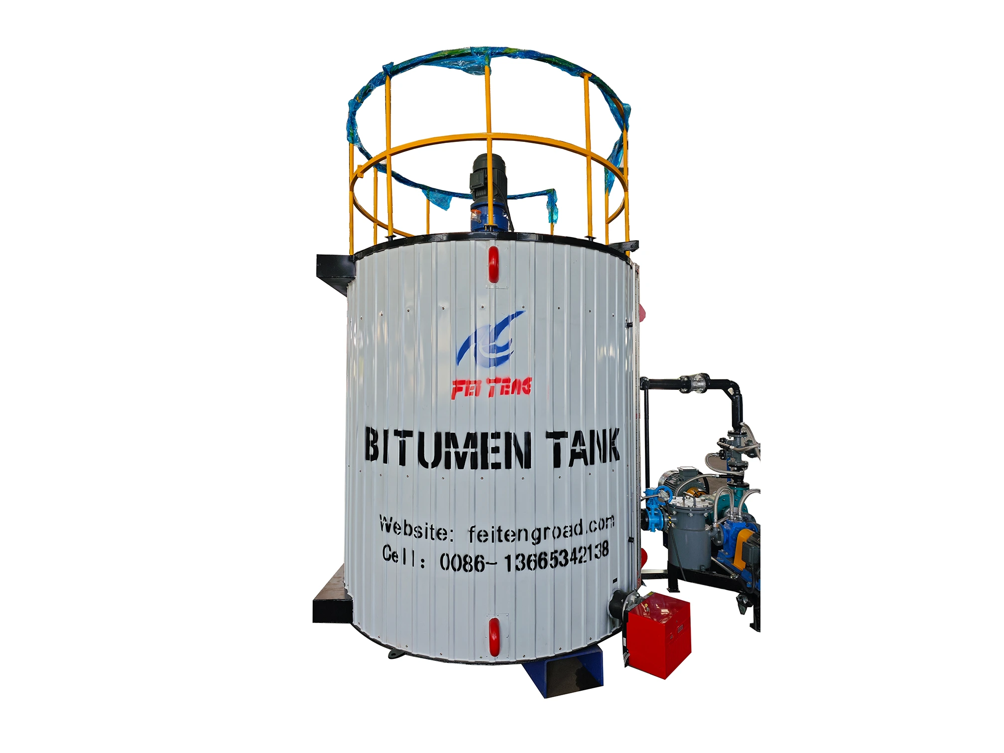
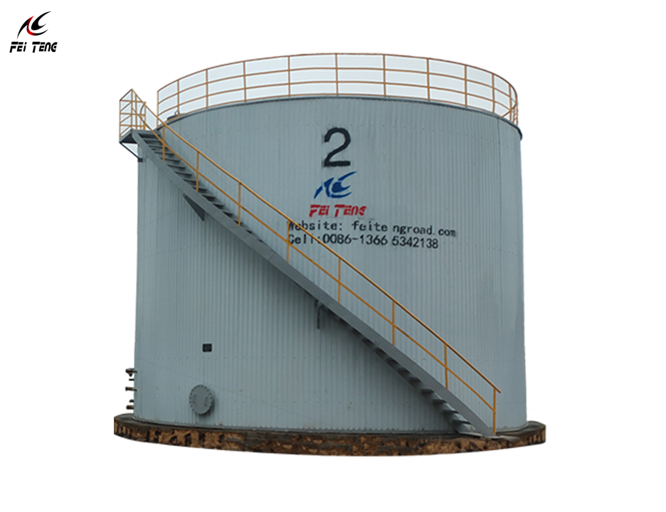
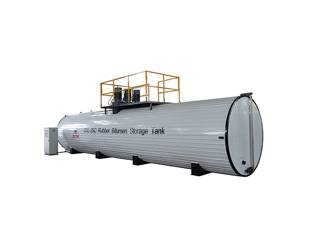
FEITENG can help coordinate bitumen pumps, heated pipelines, storage tanks and thermal oil systems as one complete transfer system.
व्हाट्सएप: +86 15335447006
ईमेल: [email protected]
वेबसाइट: www.bitumenmachine.com
 हिन्दी
  English
  Deutsch
  Español
  Tiếng Việt
  العربية
  Français
  Português
  Русский
  বাংলা
বাংলা  Українська
  Bahasa Indonesia
  اردو
اردو