

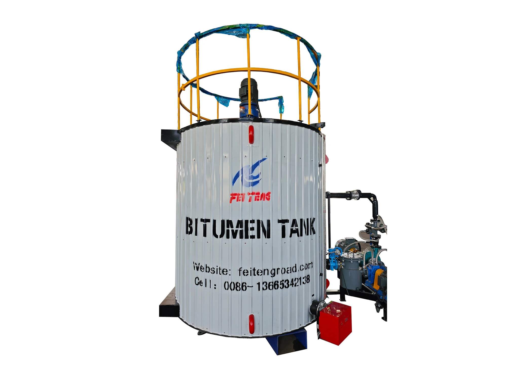
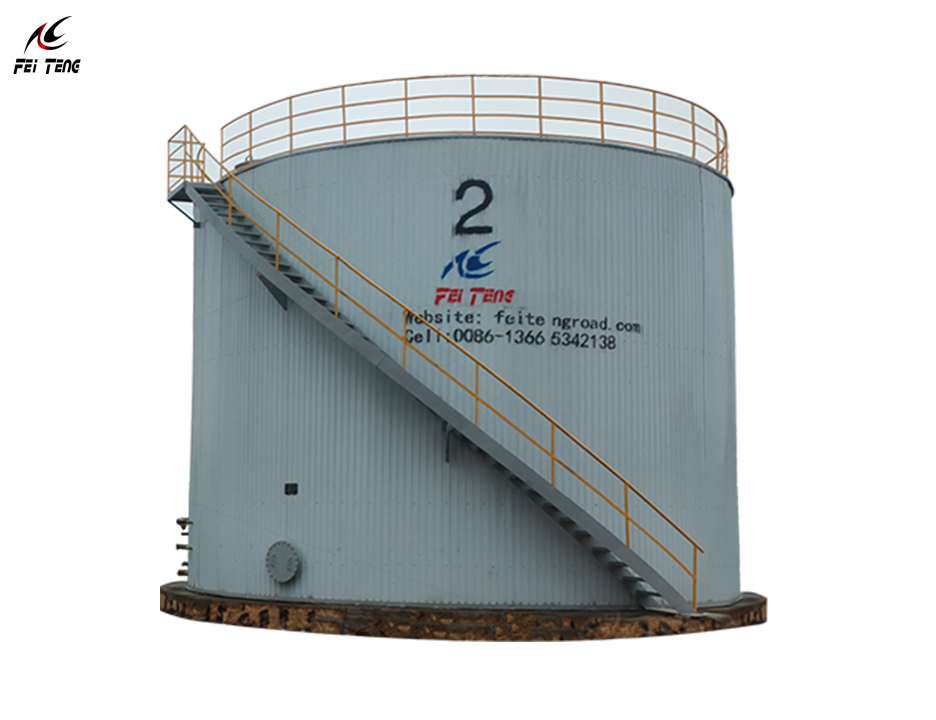


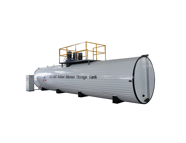


Bitumen storage tank insulation is not simply a matter of selecting 50 mm or 100 mm mineral wool. The appropriate thickness depends on tank geometry, storage temperature, climate, insulation conductivity, wind exposure, roof details and operating schedule. This guide shows how to estimate heat loss for a bitumen tank, compare insulation thicknesses and convert the result into a preliminary heating-energy budget.
What causes heat loss from a bitumen storage tank?
A heated bitumen tank loses energy through its cylindrical wall, roof, supports, nozzles, access points and connected piping. Exposed surfaces also transfer heat to surrounding air through convection and radiation. Wet or compressed insulation, damaged cladding and thermal bridges can significantly increase actual losses. A ground-supported tank bottom behaves differently from an exposed roof: its loss depends on foundation layers and soil conditions, so it must be assessed separately.
The distinction between temperature maintenance et initial heat-up is important. Insulation reduces the continuous heat needed to hold bitumen at temperature; it does not eliminate the much larger energy needed to heat a full tank from a cold starting condition. For initial heat-up and heater selection, see our thermal oil heater capacity calculation guide.
Simple heat-loss formula for early-stage estimates
For a relatively flat insulated surface, a preliminary steady-state estimate is:
Q = A × ΔT / (t/k + 1/ho)
Here, Q is heat loss in watts (W), A is area in m², ΔT is the approximate inside-to-ambient temperature difference in K or °C, t is insulation thickness in metres, k is insulation thermal conductivity in W/(m·K), and ho is the combined outside heat-transfer coefficient in W/(m²·K). This simplification neglects shell and internal-film resistance and treats the hot-side insulation temperature as approximately the bitumen temperature. It is a screening calculation, not a certified design.
For a cylindrical tank wall, use the more accurate radial-resistance approach:
Qside = 2πLΔT / [ln(r2/r1)/k + 1/(hor2)]
where L is straight-side tank height, r1 is the outside radius before insulation and r2 = r1 + t. For a flat roof, a simple area-based model may be used. Detailed designs should include radiation, temperature-dependent conductivity, internal convection, cladding emissivity, roof geometry and local weather conditions. The US Department of Energy’s industrial tank methodology includes these thermal resistances; the National Insulation Association also publishes cylindrical insulation calculations.
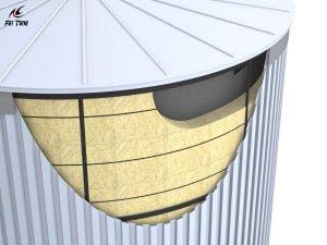
Assumptions for the 50 m³ and 100 m³ examples
The following comparisons are illustrative engineering calculations, not measured FEITENG equipment performance or universal insulation specifications.
| Input | Assumed value |
|---|---|
| Stored bitumen temperature | 150°C |
| Outdoor ambient temperature | 20°C |
| Temperature difference | 130 K |
| Insulation conductivity, k | 0.045 W/(m·K), held constant for comparison |
| External heat-transfer coefficient | 8 W/(m²·K), illustrative |
| 50 m³ tank geometry | 3.2 m diameter; 6.22 m cylindrical height |
| 100 m³ tank geometry | 4.0 m diameter; 7.96 m cylindrical height |
| Included surfaces | Vertical cylindrical wall and flat roof |
| Excluded losses | Bottom/foundation, supports, thermal bridges, piping, openings and wind-driven variation |
The dimensions are mathematical examples chosen to yield approximate nominal volumes, not FEITENG model drawings. In a real project, verify hot-service conductivity at the relevant mean insulation temperature; nominal ambient-temperature material values may not apply at 150°C.
50 mm vs 100 mm vs 150 mm insulation: calculated comparison
| Nominal tank volume | Isolation | Modelled loss | 24-hour energy |
|---|---|---|---|
| 50 m³ | 50 mm | 7.53 kW | 180.8 kWh/day |
| 50 m³ | 100 mm | 4.02 kW | 96.5 kWh/day |
| 50 m³ | 150 mm | 2.76 kW | 66.3 kWh/day |
| 100 m³ | 50 mm | 11.98 kW | 287.6 kWh/day |
| 100 m³ | 100 mm | 6.38 kW | 153.1 kWh/day |
| 100 m³ | 150 mm | 4.38 kW | 105.0 kWh/day |
For the illustrative 100 m³ tank, increasing insulation from 50 mm to 100 mm lowers the modelled wall-and-roof loss from 11.98 kW to 6.38 kW. Increasing from 100 mm to 150 mm lowers it further to 4.38 kW. The additional thickness offers diminishing absolute savings. These numbers should not be reported as an expected percentage reduction in a real plant because piping, thermal bridges, roof construction, and operating practices may dominate.
How to estimate daily heating energy and fuel cost
For a tank operating steadily at temperature:
Daily thermal energy (kWh/day) = modelled heat loss (kW) × operating hours (h).
If the 100 m³ example uses 100 mm insulation, its modelled heat loss is 6.38 kW. Over 24 hours, that equals approximately 153 kWh of delivered thermal energy per day for the surfaces included in the model. It is not 153 kWh of electrical consumption unless electric resistance heating is used and other losses are ignored.
For a fuel-fired system, a basic fuel-input estimate is thermal energy ÷ seasonal system efficiency. At an assumed 80% net efficiency, 153.1 ÷ 0.80 = approximately 191.4 kWh/day of fuel energy input. Multiply by the local fuel tariff per kWh of fuel energy to estimate cost. Verify the fuel’s heating-value basis, burner performance, standby losses, and operating schedule before preparing a budget.
Why climate and tank geometry change the answer
For a fixed insulation and surface-transfer assumption, heat loss rises approximately in proportion to the temperature difference. A 150°C tank at 0°C ambient has a larger thermal driving force than the same tank at 20°C. However, wind changes the external heat-transfer coefficient, and rain, damaged cladding or wet insulation can invalidate a simple proportional adjustment.
Nominal capacity alone is not enough to calculate heat loss. Two 100 m³ tanks with different diameter-to-height ratios have different exposed areas. A horizontal tank, vertical site-assembled tank and containerized mobile tank require separate geometry and support-loss assumptions. If you are still selecting tank volume, use our calcul de la capacité d'un réservoir de stockage de bitume before finalizing insulation.
How to choose insulation material and thickness
For industrial bitumen tanks, designers frequently evaluate mineral-wool insulation with weather-resistant metal cladding, but the final system must meet the operating temperature, fire classification, corrosion-management and local engineering requirements. Ask suppliers for declared thermal conductivity at the working mean temperature, moisture performance, compression strength where relevant, and suitable installation details.
Thickness selection should compare installed capital cost against annual heat-energy savings, not rely on a universal rule such as “100 mm is always enough.” Include access hatches, nozzle boxes, pipe penetrations, removable maintenance covers, tank supports and roof-to-shell junctions in the specification. Cold-region projects may need particular attention to freeze protection, water ingress and weatherproofing.
Thermal oil heating vs electric heating: what changes?
The tank’s insulation-related thermal loss is governed primarily by temperature, geometry and envelope design, not by the source of heat. A thermal oil loop and an electric heater both need to replenish that loss. What differs is the source efficiency, available power or fuel supply, control strategy, installation cost and distribution losses.
For multi-tank systems, thermal oil circuits may offer a centralized solution, but boiler standby losses and heated piping must be included. Electric systems avoid fuel-burning equipment at the tank but may carry high demand charges or power-supply constraints. See our bitumen storage tank engineering guide for wider design considerations.
Information to include in an insulation and heating-system RFQ
- Number of tanks, nominal capacities, orientation, drawings and exposed surface areas.
- Bitumen grade, normal holding temperature, minimum startup temperature and maximum permissible temperature.
- Site location, minimum and average ambient temperature, wind exposure and weather conditions.
- Required heating-up time and operating hours per day.
- Insulation material, declared conductivity versus temperature, nominal thickness and cladding details.
- Foundation insulation, roof detail, thermal bridges, manholes, pipework and heat tracing.
- Fuel type, electricity price, expected system efficiency and required redundancy.
- Maintenance access and measurable temperature or energy performance acceptance criteria.
Foire aux questions
How much heat does a 100 m³ bitumen tank lose?
There is no single figure based on capacity alone. In the illustrative geometry and conditions above, the calculated sidewall-and-roof loss is 6.38 kW with 100 mm insulation. Actual loss must also include bottom, supports, piping, penetrations and environmental effects.
Is 100 mm insulation better than 50 mm?
Generally, thicker insulation reduces conductive loss when the material and conditions are comparable. Whether the extra thickness pays back depends on installed cost, climate, operating hours and energy tariffs.
Can tank heat loss determine thermal oil boiler size?
Only the temperature-maintenance portion. Heater sizing must also allow for initial heat-up, concurrent tank loads, circulation and heat-exchanger performance, pipelines, controls and reserve capacity.
Does mineral-wool conductivity stay constant at 150°C?
No. The constant conductivity used in this worked example simplifies comparison. Obtain supplier data at the appropriate mean insulation temperature for final calculations.
Conclusion: evaluate insulation as part of the complete tank system
Heat-loss calculations help buyers compare insulation options, but reliable performance depends on the complete bitumen storage and heating system. FEITENG can review tank size, target temperature, local conditions and heating method when discussing a project-specific configuration. Contact FEITENG through BitumenMachine with your tank drawings and operating requirements for an engineering discussion.
Calculation disclaimer: all tabulated results are preliminary illustrative steady-state estimates, not equipment guarantees. Final design should follow applicable codes and be checked by a qualified thermal/mechanical engineer using manufacturer data and site-specific conditions.
 Français
 English
 Deutsch
 Español
 Tiếng Việt
 العربية
 Português
 Русский
 हिन्दी
 বাংলা
 Українська
 Bahasa Indonesia
 اردو